
Benefits of Telco Cloud
- High network bandwidth;
- Efficient resource utilization;
- Increased fault tolerance;
- Flexibility and scalability of the operator’s infrastructure;
- Readiness for new technologies and workloads.
Telco Cloud architecture using vStack as an example
vStack Telco Cloud is an industry solution from vStack vendor, designed for building modern data centers of telecom operators, with increased bandwidth requirements, allowing to place most network functions (CG-NAT, BRAS, DPI) in the virtual infrastructure.
SSG VNF implementation scenario
SSG architecture assumes load parallelization between separate physical processor cores. Exactly physical ones, because traffic processing requires high performance and consistently low latency. In case of using virtual cores it is impossible to fulfill these conditions.
Below let’s study an example of SSG CG-NAT VNF cluster organization using SSG L3B balancer in Telco Cloud.
Let’s allocate the following Virtual Machines:
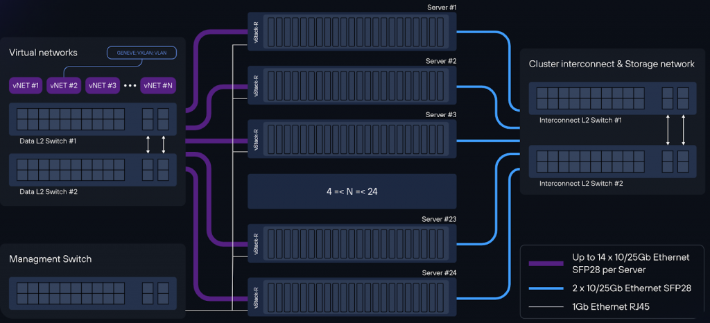
- SSG CG-NAT: 12 physical cores. Each VM is allocated 2x25G SR-IOV virtual ports in on-stick mode. Thus, the bandwidth is 25Gbps (in+out) including redundancy. The card from which the ports are allocated must be installed in the PCIe slot of the CPU where the physical cores for the VM are allocated.
- SSG L3B: 12 physical cores. Each VM is allocated 2x25G SR-IOV virtual ports in on-stick mode. Thus, the bandwidth is 25Gbps (in+out) including redundancy. The card from which the ports are allocated must be installed in the PCIe slot of the CPU where the physical cores for the VM are allocated.
The cluster is expandable up to 60 VM SSG CG-NAT and up to 10 VM SSG L3B, with a maximum throughput of 1.5Tbps.
Traffic flow diagram with balancing based on SSG L3B
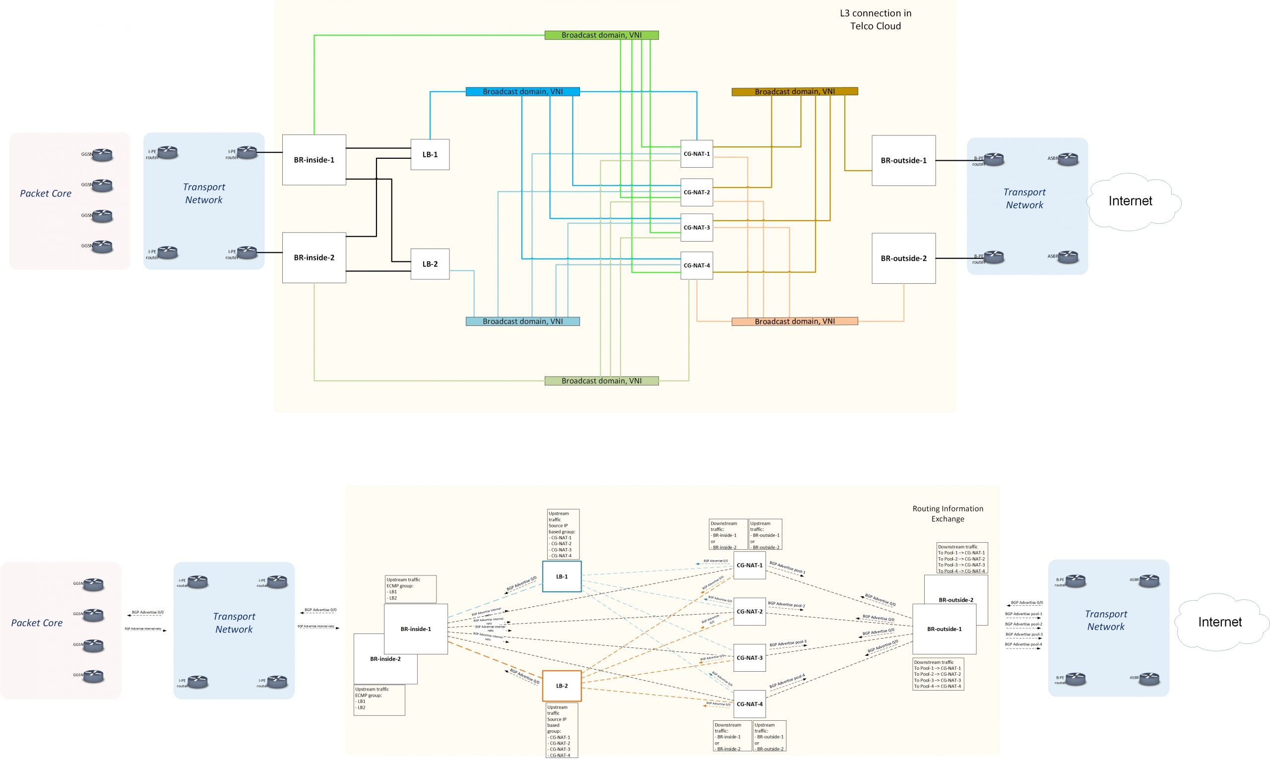
Traffic flow in the direction subscriber -> WAN (upstream)
- Each SSG L3B announces a default gateway to BR-inside (BR-inside-1, BR-inside-2) via BGP.
- Each SSG CG-NAT announces a default gateway to the side of each SSG L3B over BGP.
- Each BR-outside announces a default gateway to the side of the SSG CG-NAT VNF cluster.
- BR-inside merges the VM cluster of SSG L3Bs into a single ECMP group. Performs balancing between the next hops of the same ECMP group at level 5 tuple flow.
- SSG L3B, upon receiving traffic from BR-inside, automatically distributes all outbound traffic from clients to the SSG CG-NAT of the VNF cluster based on source IP address.
- The SSG CG-NAT performs address translation, performs routing (changes MAC addresses), and sends the packet to BR-outside-1 or BR-outside-2 based on the received BGP routes. The SSG CG-NAT VNF cluster combines the edge routers into one ECMP group.Round robin balancing is performed at the flow level on all Multipath routes so that packets belonging to the same 5 tuple flow will be routed to the same BR.
Traffic flow in the direction WAN -> subscriber (downstream)
- BR-inside announces to the SSG L3B cluster via BGP the subnets of the subscribers it serves (“Users” in the diagram).
- Each SSG CG-NAT node announces to the BR-outside (BR-outside -1, BR-outside -2) the served public NAT pool over BGP.
- The BR-outside forwards traffic to the SSG CG-NAT announcing the pool based on the routes received.
SSG CG-NAT performs reverse address translation, performs routing (changes MAC addresses to those of the corresponding BR-inside) based on the routes received from each BR-inside over BGP. - SSG CG-NAT, when receiving the same routes from BR-inside, performs round robin balancing at flow level on all Multipath routes so that packets belonging to the same 5 tuple flow will be routed to the same BR-inside. Since no balancing is required for DOWN Stream traffic, DOWN Stream traffic bypasses the L3B cluster.
Fault tolerance
If a VM SSG L3B fails, the current BGP session between the specific L3B and the BR-inside is interrupted. ECMP will allow traffic to be evenly redistributed between the remaining VM SSG L3Bs.
In case of failure of the VM SSG CG-NAT, the current BGP session is interrupted, and traffic from Source IP, which was going to the fallen CG-NAT, will be evenly redistributed to the remaining CG-NATs, without changing the balancing on the LBs of other subscribers. This is achieved by using the resilient hashing variation algorithm, only considering Source IP.
Adding a new VM SSG CG-NAT to the pool is accomplished:
- At the vStack virtual infrastructure level (VM import/creation/administration): manually or using the appropriate cloud images supported by vStack Telco Cloud.
- At VM OS level (component installation/configuration): manually or using appropriate scripts (bash/python or other supported OS). Configuration management tools are also supported.
Once a BGP session of a new SSG CG-NAT is established with each SSG L3B, the new SSG CG-NAT is added to the ECMP group. The SSG L3B distributes traffic with the new SSG CG-NAT taking into account the resilient hashing variation algorithm.